The Engineer Tutor
Learn from our Experience


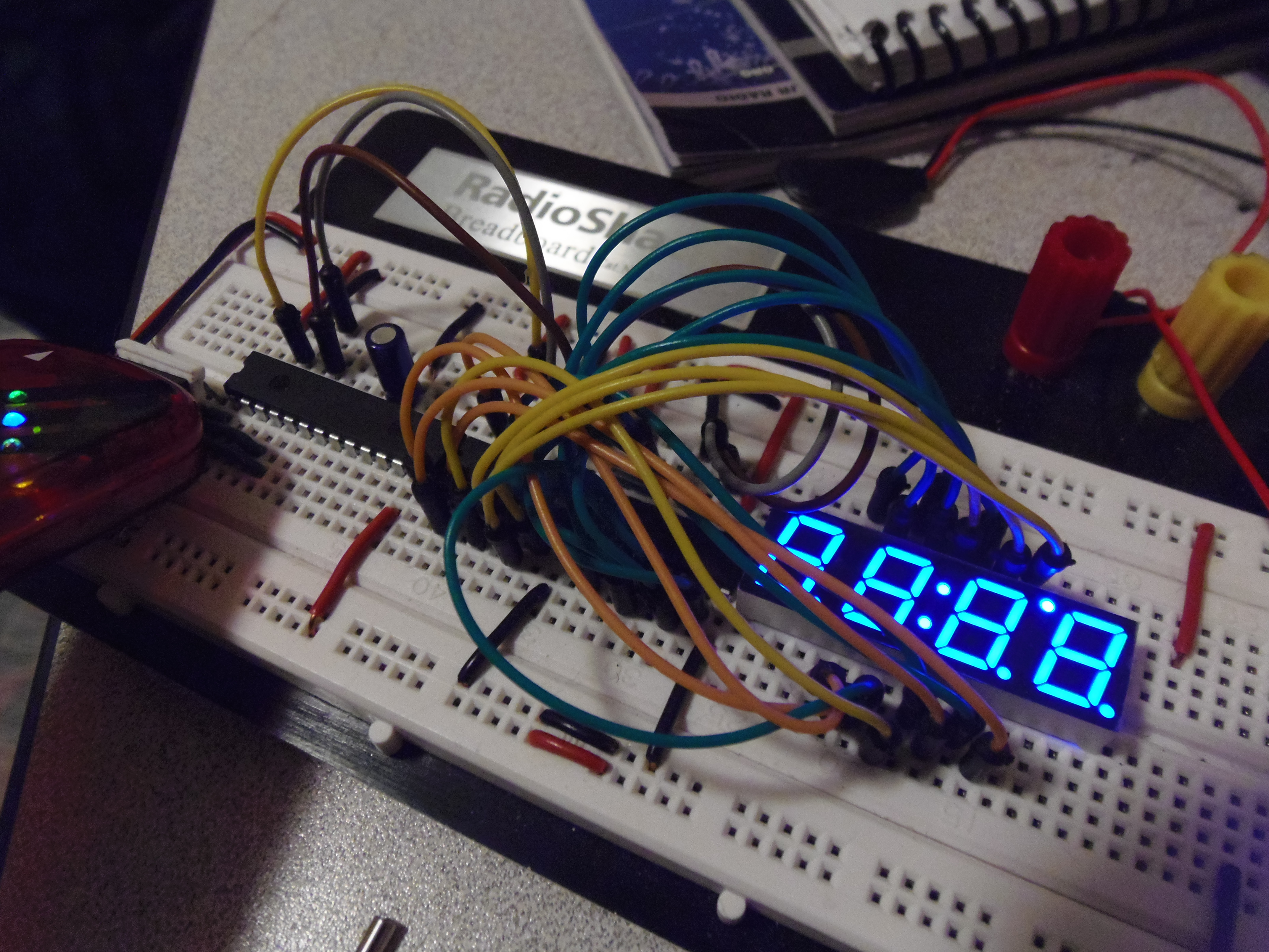
After adding more LEDs and using a shift register, what else could you do? The third improvement to Blinkie is to use a 4-digit 7-segment display.
7-segment displays are just 7 specially arranged LEDs to make it possible to display digits. I will be using a blue LED display COM-09481 that has 4 digits, decimal points between the digits, a colon between the middle digits, and an apostrophe between the last two digits.
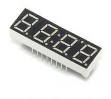
COM-09481 (click to enlarge)
There are 16 pins in this component. On the belly side you can see the pin numbering:
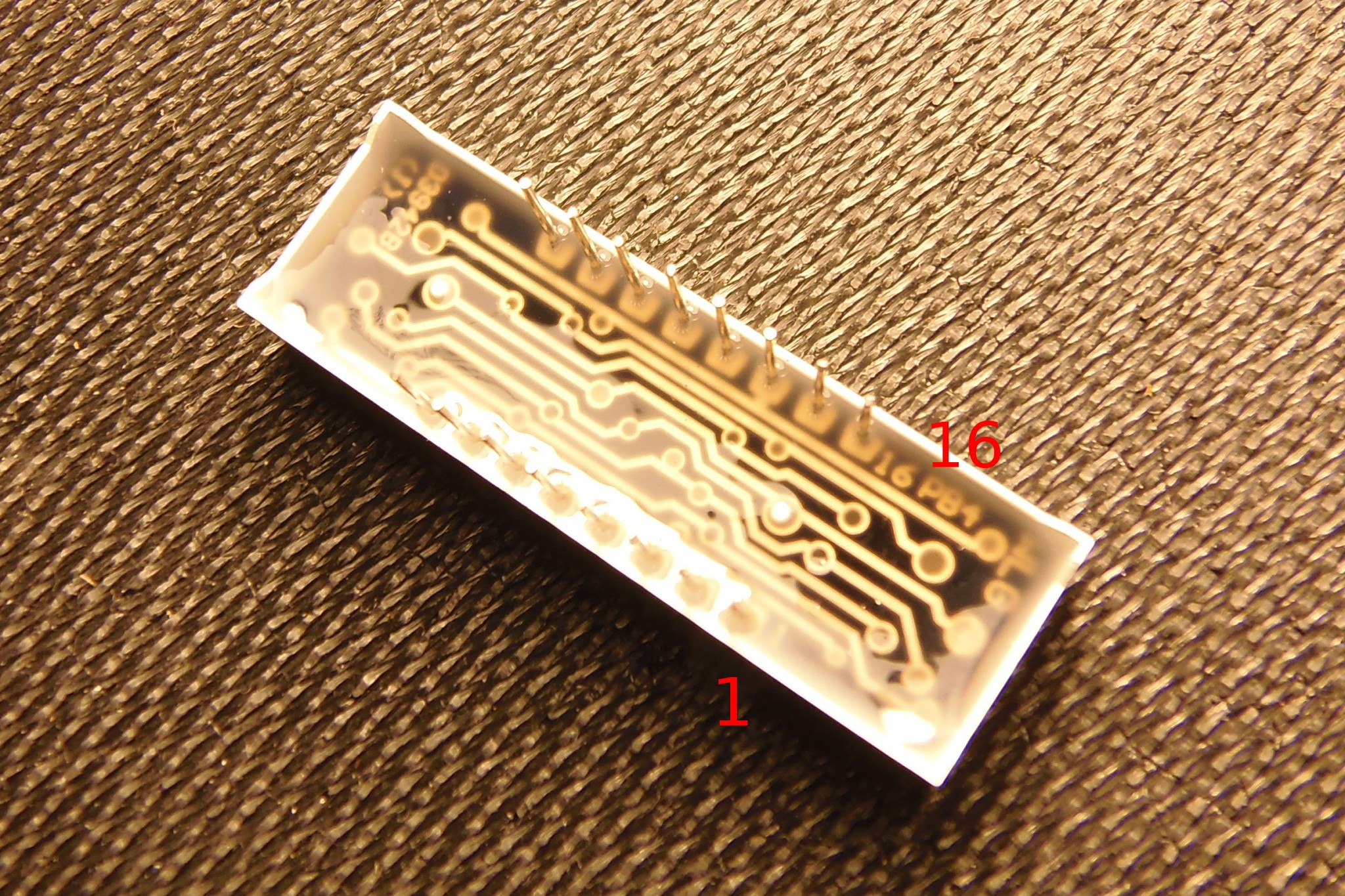
COM-09481 Belly Side (click to enlarge)
So basically, the pin on the bottom left is 1, and the pin on the top left is 16:
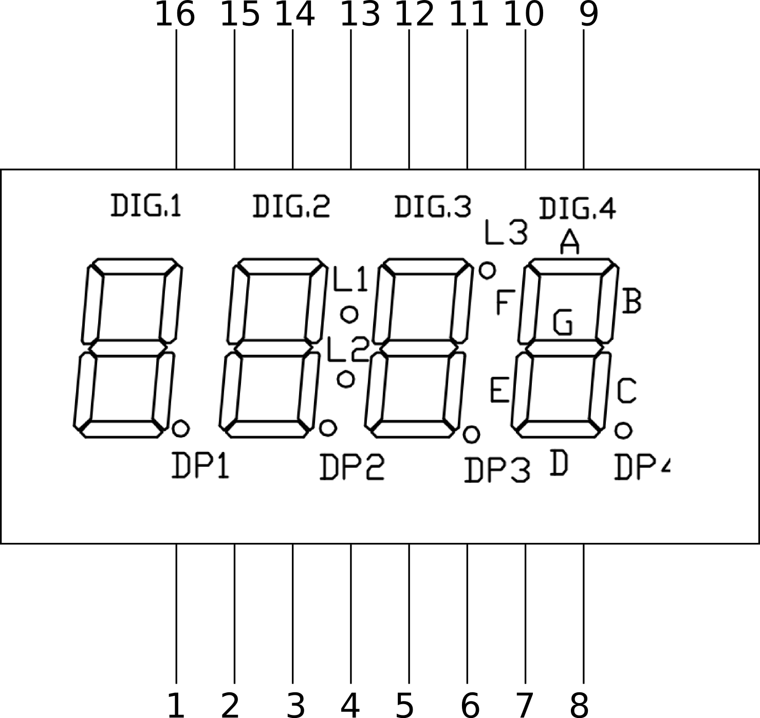
COM-09481 Diagram (click to enlarge)
In the last digit you can see the letter assignments for each segment of the digits.
There are 35 LEDs in that component. You might wonder “How can I light up 35 LEDs with only 16 pins. The answer is multiplexing.
As you can see in the image below, you have 4 pins for each digit (pins 1, 2, 6, and 8). Then you have 7 pins for each segment (A-G) in the digit. So to set all segments for digit 2 on, you would set pins 12, 16, 13, 3, 5, 11, and 15 (all segments) high, in addition to pin 2.
COM-09481 Pinout (click to enlarge)
You might have noticed, we need two shift-registers so that we can control 16 pins. (Really, we could skip using a shift register because our PIC has 16 outputs. But this is more fun.)
First I connected pins 10 (MR) and 16 (Vcc) to +. Then I enabled output by connecting pin 13 (OE) to -. You could control this from your PIC but I just want it enabled always. I also connected pin 8 (GND) to -.
After that I connected two wires from the PIC to the shift register.I connected ST_CP (pin 12) from shift register 1 to shift register 2 (same pin). Then I connected SH_CP (pin 11) of the shift register 1 to the same pin on shift register 2. Then I connected Q7’ (pin 9) of the shift register 1 to the DS (pin 14) of the shift register 2. The two shift registers are now chained.
I had to change my code because my patterns can now be 16 bits long.
I converted my loop to check bits to handle 16 bits,
for (i = 0; i < 16; i++) {
and converted the patterns
doStep(0x2000);
doStep(0x8000);
I now have 16 output pins, 8 in each shift register. I will use the lower byte for the segments (A-G) and the decimal points (DP1-DP4). I will use the higher byte for multiplexing the digit (DIG1-Dig4), and the colon and the apostrophe.
I connected Q0-Q7 of the shift register 2 to the A-G and decimal point of the display.
Then I connected the Q0-Q7 of the shift register 1 to the digits (DIG1-DIG4) and the rest of the pins.
Here is the schematic:
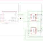
4-digit 7-segment display Schema
Wow that is a lot to keep track of. Let’s try to simplify it.
The lower byte is for the segments.
| Digit | Binary | Hex |
|---|---|---|
| 0 | 0000 0000 0000 0011 | 0x0003 |
| 1 | 0000 0000 1001 1111 | 0x009F |
| 2 | 0000 0000 0010 0101 | 0x0025 |
| 3 | 0000 0000 0000 1101 | 0x002D |
| 4 | 0000 0000 1001 1001 | 0x0099 |
| 5 | 0000 0000 0100 1001 | 0x0049 |
| 6 | 0000 0000 1100 0001 | 0x00C1 |
| 7 | 0000 0000 0001 1111 | 0x001F |
| 8 | 0000 0000 0000 0001 | 0x0001 |
| 9 | 0000 0000 0001 1001 | 0x0019 |
| . (decimal point) | 0000 0000 1111 1110 | 0x00FE |
The upper byte is for control and the other dots.
| Control / Digit | Binary | Hex |
|---|---|---|
| DIG1 | 1000 0000 0000 0000 | |
| DIG2 | 0100 0000 0000 0000 | |
| DIG3 | 0010 0000 0000 0000 | |
| DIG4 | 0010 0000 0000 0000 | |
| Colon | 0000 1000 0000 0000 | |
| Apostrophe | 0000 0010 0000 0000 |
To create the patterns, then I need to combine the upper and lower bytes. For example, to write a 0 in digit 1, I need to write DIG1 | ZERO to the shift register.
Here is the complete listing:
/*
 * File:   blink.c
 * Author: viitanenm
 *
 * Created on April 5, 2013, 11:45 AM
 */

#include <stdio.h>
#include <stdlib.h>
#include <p24FJ64GB002.h>

#define DELAY 1000

#define DS_low()  LATB &=~0x8000
#define DS_high()  LATB |=0x8000

#define ST_CP_low() LATB &=~0x4000
#define ST_CP_high() LATB |=0x4000

#define SH_CP_low() LATB &=~0x2000
#define SH_CP_high() LATB |=0x2000

#define CHECK_BIT(var,pos) ((var) & (1<<(pos)))


#define DIG1 0x8000
#define DIG2 0x4000
#define DIG3 0x2000
#define DIG4 0x1000

void doStep(unsigned int pattern);
void setLEDs(unsigned int pattern);
void selfTest();
void iterateAllDigits(unsigned int digit);

/*
 *
 */
int main(int argc, char** argv) {

    TRISB = 0x0000;
    T1CON = 0x8030;

    // reset everything
    LATB = 0x0000;
    doStep(0x00);
    while (1) {
        selfTest();
    } // main loop
    return (EXIT_SUCCESS);
}

/**
 * Displays numbers from 0 to 9 on each digit of the display
 */
void selfTest() {
    iterateAllDigits(0x0003);
    iterateAllDigits(0x009F);
    iterateAllDigits(0x0025);
    iterateAllDigits(0x000D);

    iterateAllDigits(0x0099);
    iterateAllDigits(0x0049);
    iterateAllDigits(0x00C1);
    iterateAllDigits(0x001F);

    iterateAllDigits(0x0001);
    iterateAllDigits(0x0019);
    iterateAllDigits(0x00FE);
    iterateAllDigits(0x0000);
    iterateAllDigits(0x0000);
}

/*
 * Sets the display for each digit
 */
void iterateAllDigits(unsigned int pattern) {
    TMR1 = 0;
    while (TMR1 < DELAY) {
        doStep(DIG1 | pattern);
        doStep(DIG2 | pattern);
        doStep(DIG3 | pattern);
        doStep(DIG4 | pattern);
        doStep(0x0800);
        doStep(0x0200);
    }

}

void doStep(unsigned int pattern) {
    setLEDs(pattern);

}

/*
 * Actually sends the data to the shift registers
 */
void setLEDs(unsigned int pattern) {
    ST_CP_low();
    SH_CP_low();
    int i;
    for (i = 0; i < 16; i++) {
        if (CHECK_BIT(pattern, i))
            DS_high();
        else
            DS_low();

        SH_CP_high();
        SH_CP_low();
    }
    ST_CP_high();
}
There are many things you could use this display for. You could, for example, make a clock.